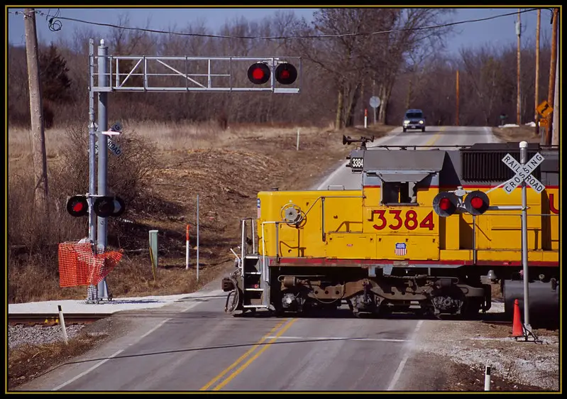
We’ve all been there at one point or other; you’re driving up to a set of railroad tracks and moments before you’re about to cross, you see its flashing lights turn on as the crossing’s gate lowers, barricading the way forward. For many, this is a mild annoyance that means they’ll be delayed several minutes as a train passes by, but have you ever wondered what sets this whole process in motion?
How railroad crossings are activated depends on what type of system that particular stretch of track utilizes. Most modern crossings are equipped with one of three systems: a track circuit system, a motion detector system, or a grade crossing predictor system. While each achieves the same results, how they operate differs widely.
In this article, we’ll explain in more detail how railroad crossings are activated for both primary systems, what components are essential to this technical process, and how they work together to ensure the safety of train passengers, drivers, and pedestrians.

How Do Different Types of Railroad Crossing Systems Work?
Oftentimes, the everyday person assumes railroad crossings must be activated by the train running over some sort of button or switch. While this misconception is understandable, and not entirely far off from reality, what many don’t realize is that railroad crossings utilize highly technical systems born from ingenious electrical and mechanical engineering, and not every railroad crossing has the same system in place.
As we mentioned previously, railroad crossings are activated by utilizing one of three systems. A track circuit system is the oldest of the three, and relies solely on electrical currents to activate and deactivate the railroad crossing mechanisms. Comparatively, motion detector and GCP systems are far more modern and send signals using electronic software paired with electrical currents and railroad shunts.
Of course, these are very concise, general explanations of how these systems work, which is why we’ve described the activation process for each in more detail below.
Track Circuit Systems
The revolutionary track circuit system installed on countless railroad tracks was first invented by Dr. William Robinson in 1872, nearly seven decades after the first steam locomotive was invented.
This system, also referred to as the three-circuit system, relies on just that; three separate circuits placed near the railroad crossing that activate and deactivate its mechanisms depending on the train’s location and the electrical current running between them.
But let’s take a step back and explain how this system is set up. Essentially, there are three circuits strategically placed along the railroad crossing tracks. One is placed in the center of the crossing at the intersection between track and road. This is referred to as the “island” and therefore, the circuit here is named “the island circuit.”
On either side of this island circuit are two additional circuits referred to as “approach circuits.” These are set a specified distance from the island circuit in order to ensure there is sufficient lead time for the railroad crossing mechanisms (ex. lights, bells, gate) to activate before the train reaches the crossing.
Now that everything is in place, let’s explain how the activation process works. As a train crosses the first approach circuit, its steel wheels and axel will bridge the electrical current that runs between the two rails. This electrical current then activates the railroad crossing, switching on its flashing warn lights and other mechanisms.
As the train continues down the track, it will travel over the island circuit, continuing the electric current and signaling to the railroad crossing machinery that the train is still present.
Once the train finally passes over the third circuit, meaning the approach circuit on the opposite side of the island circuit and the railroad crossing, its wheels and axel will once again complete the electrical current and shut off the railroad crossing mechanisms.
Motion Detector System
Motion detector systems are significantly more technical than the overtly simple track circuit systems because they utilize circuits in addition to electronic software and railroad shunt apparatuses to signal the presence of a train in time to activate railroad crossing mechanisms.
Again, we’ll need to break down and define some of these components to fully understand how everything works.
As opposed to the two approach circuits present in a track circuit system, motion detector systems utilize termination shunts. These are usually PVC pipes consisting of C-clamps and low resistance wires filled with diodes and capacitors.
One termination shunt apparatus is placed on either side of the island circuit (much like the approach circuits) and each apparatus features two wires, separately connected to each of the track’s rails. This allows the termination shunt to create a short-circuit between the rails and simulate the track conditions of a train passing and creating a low resistance connection.
In addition to the termination shunts, you’ll find a series of electronic devices containing vital software within small sheds known as bungalows. These are responsible for receiving signals and sending them to the railroad crossing mechanisms.
Now, let’s put it all together. When a train isn’t present, an alternating current (AC) signal is constantly injected into the rails through a transmitter lead. As the train passes the first detector circuit/termination shunt, its wheels and axel will shunt the two rails and begin changing the impedance of a coded circuit in the track.
This, in turn, sends a signal to the electronics in the bungalow or signal box that a train is approaching the railroad crossing. These electronics then signal and activate the crossing mechanisms and will continue to signal its presence as long as the impedance keeps changing.
Once the train has passed the second termination shunt, the current will return to its normal frequency, meaning the track impedance has stopped. The motion detectors electronics will register the train’s passing and signal for the railroad crossing mechanisms to turn off.
Grade Crossing Predictor (GCP) System
Luckily, a GCP system works very similarly to a motion detector system (sometimes the two systems are even paired). The biggest difference here is that the motion detector device and its associated electronics are replaced with a GCP device.
This device contains two plug-in circuit cards (one for normal use, one as a backup in the event that the “normal” card fails) and is connected to the track’s individual rails using wires along with other electronic devices (oftentimes those directly connected to the railroad crossing’s mechanisms).
Again, an AC current is run through the rails from the GCP out to termination shunts further down the track, but where the GCP differs is that once a train crosses the first termination shunt, the GCP system’s software can predict the train’s speed and distance.
This allows it to activate the railroad crossing mechanisms within the mandatory lead time (which is 20 seconds according to the Federal Railroad Administration for all mainline crossings) and deactivate them once the train passes the second termination shunt.
Final Thoughts
While some railroad crossings are more unique and innovative with the systems, electronics, and software they use for activation, most implement something that resembles the three options detailed here. As you can see, this process entails much more than the simple push of a button, but these feats of mechanical and electrical engineering are what’s necessary to keep railroad crossings as safe as possible.